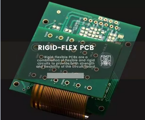
Rigid-flexible PCBs are a combination of flexible and rigid circuits to provide both strength and flexibility of the circuit board. Rigid-flexible PCBs are made of flexible layers of substrate materials which are joined together using a pre-preg bonding sheet or film and afterward attached to the rigid part of the PCB. The integrated circuit created by the combination of rigid and flexible circuits is connected via cut-through holes, having the finest features of both flexible and rigid circuits.

In rigid-flexible PCBs, the flex PCB is usually one-sided whereas the rigid PCB might be a multilayer PCB. The rigid part of the PCB provides an area where components are soldered, while the flexible part of the PCB is used to maintain connections with the rigid part of the board. The major reasons for creating rigid-flexible circuits are improved flexibility, a minimal thickness of the flex, and reduced cost of the parts of a rigid-flexible circuit. Other reasons are:
- It Improves the circuit’s ability to transmit signals with no loss
- It allows controlled impedance which offers consistent high-frequency performance.
- Eliminates connection issues like cold joints
- Minimizes weight
- Frees space in the Board for other electronic components
All rigid-flexible PCBs are divided into various zones consisting of different layers and materials. The Rigid zones in the integrated circuitry could have more layer counts than the flexible zones. The materials used as substrate changes also from FR-4 into polyimide in the transition zones. Complex designs mostly change from rigid into flex and then to rigid several times. As the transition takes place, the overlapping of the rigid d-flexible materials requires the cut-through holes to separate from the transition zones to maintain the integrity of the process. In addition, a lot of rigid-flexible designs include aluminum stiffeners or stainless steel that supports the components and connectors.
