
Many contemporary electronics nowadays use press-fitting component technologies to provide their products with additional features. Press-fit technology provides a compatible interface among a PCB and a padded panel with a single pin or interface that removes necessity solder.
What is a Press-Fit Hole:
Press-fit holes are placed in holes with a tolerance stricter than the +/-0,10mm norm. The press-fit hole size fits the connection leads, which are not soldered and forced into the hole. The tolerances are highly specified and tighter than the norm to permit the result and hole to precisely fit.
The average PTH tolerances depend on the kind of connection that the manufacturer specifies.
It is thus very important that such tolerances be accurately described in your PCB design and that the “Press-fit” parameter is verified for details in the order.
How does a press-fit hole work?
Press-fit compatible pin link is often used to give mechanical and electrical connections from a PCB to a circuit board that subsequently provides an electric and mechanical board-by-board connection. Because these pin interconnections carry both mechanical and electrical loads, the long-term durability and stability of the connection-dependent pin and PCB via (PTH) interference is crucial. However, compared to the Ball Grid Array (BGA), the press-fit pin connection still has quite a few unknowns about degradation processes. This research analyses criticism pins with a similar structure but with differing beginning microstructures and detects areas of severely deformed plastics. Segments and subtest and rear electron diffraction (EBSD) were used to evaluate and analyze the bonding power, microstructural development, and influence of thermo-mechanical cycling. The findings showed that the initial microstructure significantly affected stress development, strain percentage, grain expansion, local malaise, hardness, and connection strength. The prolonged thermocycling test was done with -40°C to 125°C cycles to determine any heat-mechanically induced deterioration potential.
What is Press Fit Tolerances:
A press-fit tolerance is an allowable measurement variation that still allows a product to operate properly.
Three essential press-fit tolerances most often seen in designs are limited sizes, unilateral and bilateral tolerances.
Press-fit surfaces:
The press-fit technique with all terminal surfaces may essentially be manufactured. Because of the limited tolerance, our clients usually pick a reactive surface, e.g. Gold or chem. Tin. Lead HAL
The free leveling of hot air solder is an option. The maker of the connection may have directly selected the surface.
Combining gold-plated pins and the organic gold surface is not advisable as this might result in higher pressure. The surface of either the pin or the circuit board is to be tinned. Only then does the press-in procedure have adequate slippage.
What is a press-fit pin?
The press-fit pinhole size has a type that may be mounted on a PCB without joining. It is utilized in PIM goods and 6-pack items. As the contact is accomplished by pushing an IGBT component over the PCB panel and exerting pressure from the base, the time needed for the assemblage process is decreased. Special presses and press-in tools are necessary. We don’t sell presses or instruments.
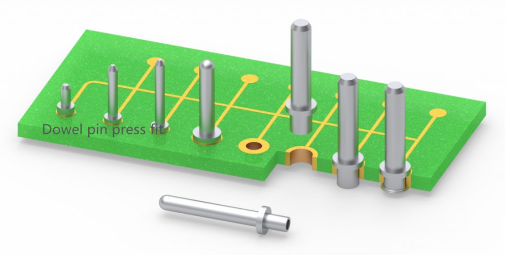
Press Fit Dowel pin:
Dowel pins press fit is solid pins, typically precise, with limitations of precise fit; they are typically used to keep the pieces in PCB to a set alignment, depending on the strength of fit to remain in place.
Some installations for solid pins need clearance and transition fittings to be attached to at minimum one of the components.
- Three criteria affect the size of the necessary hole:
- The dowel tolerance
- The fitness required
The hardness of the parts to be fitted with the dowel pinhole size.
Dowel pin press fit tolerance:
Dowel pin press-fit tolerance has conventional m6 tolerance, the tolerance range, which complies with ISO and DIN standards. The m6 tolerance is a ‘more tolerant’ range and is usually used for the interruption. The minus tolerance levels h7 and h8 are also accessible.
Dowels press-fit in blind holes:
When interference is installed in a blind hole, the air pressure in the hole is increased. It is suggested that the dowel have an air discharge plane over its entire length to avoid the dowel from being expelled under compressed air pressure or from bursting into the component it is driven.
Recommended hole sizes:
It is crucial to follow the directions on the hole diameter offered by different manufacturers and standard organizations, and the data from this source comes from our website and datasheets. However, in the conditions of a given application, the user should determine the hole size within the press-fit hole tolerance range authorized to adopt since this might significantly alter the pin’s performance.
The main premise is that the pin or dowel needs much higher strength at the level of the hole tolerance than at the high.
This has the following implications;-
- The higher the insertion force needed, the harder the assembly and the danger that the surrounding region of the hole will be damaged or overstressed are larger
- The harder the pin is inserted, the stronger it stays in place. Therefore, it might be useful to set a minimum hole size for situations where vibration is considered.
When a sliding or tolerance fit is needed, the dowel must have a precise floor, and the hole should be reamed.
The connection between the pin diameter and the hole diameter must consider the flexibility of the dowel and the material in the hole and varies more correspondingly than depending on the length of the dowel itself.
Press-Fit Bushings:
Press-fit bushing design and construction is an ordinary approach for retaining coils by interference from the loop to the coil. There was a mistake. The action of pressing or shrinking the bushing in the hole causes the coating, owing to the compressive pressures, to decrease in size.
Press-fit Bushing hole size:

Do not utilize severe interference fittings for press-fit bushings hole size to prevent jig-plate or bush deformation. For bushing installation holes, the use of a jig borer or carbide insert is recommended. Standard throwing reamers should give the desired hole tolerance with additional tolerance.
Additional variables to consider about the preparation of the installation hole:
- Headed bushings necessitate less meddling to withstand the thrust of the drill;
- Longer covers with thicker panels needless interference,
- Thin wall coats are more susceptible to deformation,
- Materials that are less pliable needless interference.
PCB Hole Design and Material use with Press-Fit:
The press-fit technique enables the installation on a printed circuit board (PCB) of a specifically stamped terminal in a plated-through hole in such a manner that a very reliable electromagnetic connection may be built without utilizing the welder.
This solderless relation, except the gender, functions as the dagger and socket pair in a connector. The socket contains flexible beams in the standard blade-and-base pair, which give the required normal strength, and the blade is stiff.
Conversely, the “blade,” termed a compliant pin, has flexible shafts in the press-fit connection, while the socket, termed the PTH, stays rigid.
The normal force is the force of the spring feature of the press-fit pin on the walls of the PCB hole. The push-in force is the force against the pin when put in the PCB. As press-fit connections on PCBs are longer permanent than blade and base connectors supposed to be detached and reassembled, the PCB must have a significantly greater standardized force following insertion into the press-fit terminal connection.
The right construction of a PCB hole and selecting suitable PCB materials play a key role in the successful working of a press-fit pin.
- Proper fabrication of PCB plated-through-hole (drill hole, copper thickness, etc.)
- Carry out PCB Hole Inspection without cross-sectioning
- PCB materials and thermal properties to fulfill the operating temperature requirements
Although the basic criteria are not complicated and cost-effective, a few core approaches guarantee that a program using press-fit technology is successful.
What are the challenges of using press-fit in PCB?
The press-fit technique offers high-quality electrical equipment without solder. This particular connection method is used to press-fit single contact components or whole assemblies with press-fit areas in metallic holes on a circuit board.
As their name suggests, press-fit contacts are forced into plated holes of the PCB with hydrogen interference between interface the hole.
Press-fit Pin interconnections from both sides of the PCB are adaptable and may be utilized for flexible double-side pin hole and SMT PCB mounting. Furthermore, when modules are reduced in size, pressure fit pins may safeguard critical components and save critical space in narrow pin designs.
Mechanical systems and processors create a lot of heat generated in the engine room or a server room. Press-fit pins offer a dependable interface to disperse thermal heat with a much higher heat barrier and lower failure rate than solder connections.
Press-Fit technology advantages
- Very high ampacity, perfect for high constant and strong currents
- Press-fit connectors are particularly stable in the environment
- Less strength connection (< 200 μ) causes low self-heating; therefore, less heat must be dispersed by the system.
- No heat generation on pressure area and no circuit board thermal stress.
- Mechanical very stable
- No cold solder junction concerns
- High mechanical forces of retention
- Circuit boards may be mounted double-sided
- Long-term dependability much greater than for solder connections
- Safer than soldering and screws
- No required adjustments in the fabrication of circuit boards
Thermal compatibility is another benefit of press-fit versus soldered wave connections. When secondary soldering is necessary, heat is inserted that might harm the PCB and the devices connected. The press-fit technique removes the excess heat cycle totally and makes secondary connections easy to remedy, ecologically sustainable, and cost-effective by employing force-only press-fit connectors. While press fit does not include soldering concerns, it has its issues, and producers compete with a range of connected devices which provide press-fit abortions of varied design complexity, consisting of varying levels of performance of substances.