Structure of a flexible PCB
As happens for rigid PCBs, FPCs can be divided into single layer, double layer or multi- layer circuits. The main elements of a single layer flexible printed circuit are the following:
-
dielectric substrate film: the base material of the PCB. The most commonly used material is polyimide (PI), characterized by high resistance to traction and temperature;
-
electrical conductors: made of copper, they represent the traces of the circuit;
-
protective finish, made with cover lay or cover coat;
-
adhesive material (polyethylene or epoxy resin), used for joining the various parts of the circuit together.
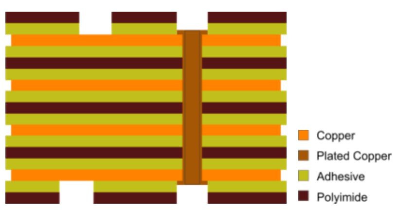
The first phase of the FPC manufacturing consists in etching the copper to obtain the traces, while the protective coating (cover lay) must be drilled so as to allow access to the soldering pads. After a cleansing treatment, the components are joined together by rolling. The external terminals/pins, necessary for the electrical connection of the circuit, are protected from oxidation by immersion in tin for welding or in gold. If the circuit has a high complexity, or requires the presence of copper ground shields, it is necessary to switch to a double layer or multi-layer FPC. The manufacturing technique is very similar to that used for single layer flexible circuits, with the difference that in multi-layer FPCs it is necessary to insert PTH (Plated Through Hole), so as to create, where required, the electrical connection between different conductive layers. The union of these materials forms a flexible circuit, in which the adhesive material serves to join the conductive tracks with the dielectric substrate or, in multi-layer flexible circuits, to join the individual layers together. In addition, the adhesive film can also be used for protective purposes, preventing moisture, dust or other external agents from corroding or oxidizing the flexible circuit. In Figure 1 we can observe the structure of a multi-layer FPC. The example shown in Figure 1 includes four conductive copper layers, PTHs (on the right side of the image) and holes for accessing the conductive material (on the left side of the image, on both external layers).

Figure 1: Structure of a multi-layer FPC (Source: Altium)
Advantages of flexible PCBs
Being flexible, FPCs can bended and flexed, allowing greater freedom in the design and operation of the application. Flexible circuits can also adapt to small or irregularly shaped spaces, a feature not supported by standard rigid circuits. Another advantage of flexible circuits is that they take up less space, reducing the weight on the application's motherboard. The optimal use of the available spaces allows also for better thermal management, reducing the amount of heat to be dissipated.
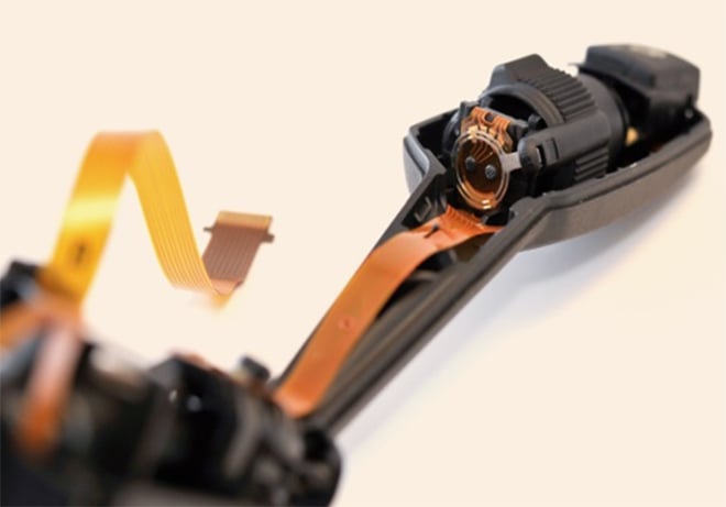
Compared to rigid PCBs, flexible printed circuits can also prove more reliable and long-lasting, especially in applications where the circuits are subjected to continuous vibrations and mechanical stress. The standard interconnection techniques, based on soldered wires and hand-wired connectors, are replaced by flexible printed circuits, characterized by extremely low weight and thickness, which are accompanied by high mechanical resistance, resistance to high temperatures and atmospheric agents as well as good electromagnetic immunity (EMI). Think, for example, of the wiring of multiple electronic devices in the automotive sector, such as dashboard, display and man-machine interfaces (rotary controls, buttons, etc.). All these devices require a reliable connection in all operating conditions of the vehicle, being furthermore subjected to continuous mechanical stresses and vibrations. In the automotive sector, flexible printed circuits guarantee reliability, durability and maintenance interventions tending to zero. Figure 2 shows an automotive application of the FPC technology, here used in a car light switch.

Figure 2: example of FPC application in the automotive industry
In addition, the use of FPC can reduce the incidence of human errors during wiring, with consequent improvement in quality and reduction of costs. FPC technology contributes to significantly reduce both the size and weight of the application, a key factor for the creation of reliable, compact and highly integrated electronic devices.
Disadvantages of flexible PCBs
Although there are several and meaningful advantages, the FPC technology has also some drawbacks, or disadvantages. First of all, compared to traditional rigid PCBs, FPCs have a high one-time initial cost. Since flexible circuits are designed for very specific applications, the initial costs related to circuit and prototype design are higher than for rigid PCBs. If the cost is a determining factor in the choice of the type of PCB, it is better to use the FPC technology only for production volumes that are not too low.
Another disadvantage is the difficulty of repairing or modifying the PCB when it needs to be reworked. In this case, in fact, it is first necessary to remove the protective film that wraps the circuit, perform the intervention and then restore the protection. Flexible PCBs are a relatively new technology and not all manufacturers are equipped to provide this type of product to their customers. Furthermore, during the assembly phase, great care must be taken, as the circuit can be easily damaged if handled incorrectly, or by unauthorized personnel.
