
The most common problems seen in Gerber files include design mismatch, insufficient clearances, obsolete file formats, unregistered layers, and incomplete files.
Gerber files are the output of circuit board design process. These files are utilized for the PCB manufacturing and assembly process. Gerbers provide information about each and every layer in the board stack-up.
- Empty Gerber Files: Believe it or not, it is possible for the designer to create Gerber files with no information in them, or “zero-byte” files. Whoever is reading the file will not know if the file is completely extraneous or if there was information in it that was accidentally deleted. Designers must check each Gerber file to make sure it contains useful information before sending it on.
- Missing or Incomplete Files: This is almost the opposite problem. Manufacturers need to know each specification related to the printed circuit board, from the size of the plated-through holes to the dimensions of the board. Any missing information will likely lead to a board that does not match the desired specifications. It’s important to make sure each necessary Gerber file is in place and accessible.
- Bad File Labeling: While not a catastrophic error, it is highly recommended that the designer name all Gerber files according to an established naming protocol the manufacturer understands. This way, the manufacturer can immediately find the Gerber file he or she needs without any confusion as to whether or not they have the right file.
- Too Many Aperture Lists: The Gerber files should ideally have a single aperture list with all the details the manufacturer needs about the tools they require for each stage of fabrication. Multiple aperture lists create confusion, can slow down manufacturing and may increase the chances of error. Also look out for designers who create aperture lists in a different format than the Gerber files, which can lead to confusion as well.
- Composite Layer Design Errors: If the designer’s software creates composite layers while generating individual layer design specifications, it’s important that the images are combined in a way that creates one Gerber file for each layer, to avoid errors.
-
Incorrect drill file format: Without the right format of the drill files, it is difficult for circuit board fabricators to import the Gerber file. These files are used to identify the size and location of the hole that has to be drilled. Drill files contain information that can be translated directly to the CNC machine. Many CAD software packages have the option of generating drill files. The header of these files should indicate the format. Such a format is known as a numerically controlled (NC) drill file. They usually have ‘.xln’ or ‘.drl’ or ‘.ile’ extension.
-
Missing board outline:Gerber files should have a clearly defined board outline. A board outline defines the dimensions of the PCB based on the customer requirement. It gives information about the exact bounds of the board edge which is required by the fabrication machine to route the individual boards from the panel. If the board outline has not been provided, there are high chances that the manufacturing is put on hold by manufacturers.Some CAD software packages don’t produce outlines by default and need to be instructed to produce one. It can be a part of the Gerber file or a general drill file.
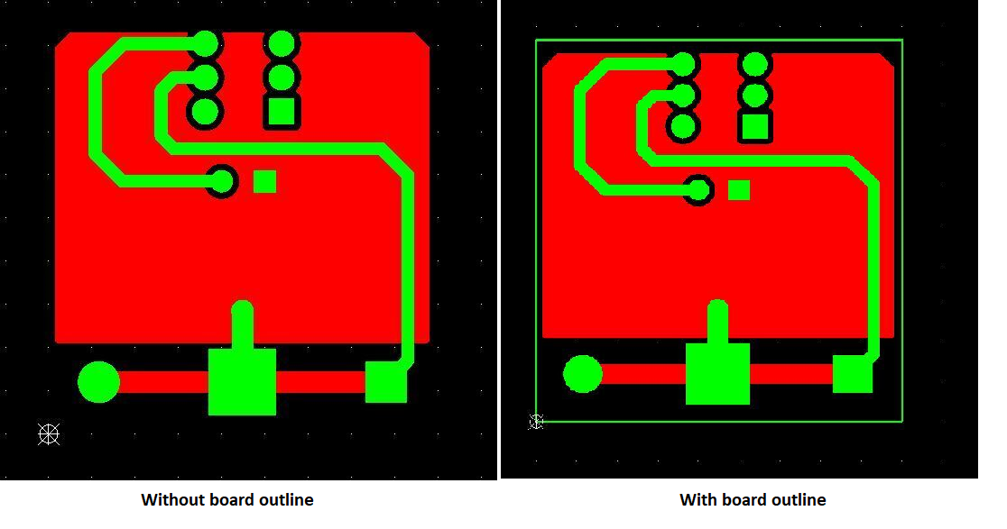 Board outline defined in the Gerber file
Of all the potential problems you may have with your printed circuit boards, Gerber file mistakes are the most inexcusable. While most PCB design errors can be avoided with more careful and focused work, Gerber file errors are the easiest to avoid. Given that the consequences of Gerber file issues can be so expensive and so time-consuming, you simply cannot allow them to happen. A few ways to help you avoid Gerber files problems include:
- Using a Gerber file viewer to check the Gerber files
- Printing a sample board to make sure the specs are correct
- Using high-definition CAD software
- Following best QA practices throughout the design process