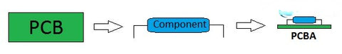
Printed Circuit Board (PCB), is the integral part of all electronic devices. This PCB has electronics components soldered upon it. These electronic components can be SMT and THT. SMT means Surface Mount Technology and THT means Through Hole Technology. The process of soldering components on PCB is known as “Assembly” in simplest terms. Thus a PCBA is the combination of PCB and components together.
Assembly Types of PCBA
There are numerous ways one can assemble electronic components on PCB. The major types of PCB assembly are mentioned in the table given below:
| Assembly Type | Diagram | PCB Design Feature |
| Single-Sided SMD | The SMD component is soldered on only single side of PCB | |
| Double Sided SMD | SMD is assembled on upper and lower both sides of PCB | |
| Single Sided Mix Assembly | Both THT and SMD are assembled on single side | |
| Mix Assembly on top and only SMD on bottom |  |
Both THT and SMD are assembled on top side while only SMD on bottom |
| THT on top and SMD on bottom | THT on one side while SMD on other |
Examples of PCB Types:
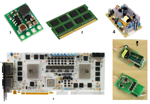
There are many applications where only SMD electronic components are assembled on single of PCB like DC-DC converter circuits, we can easily found them in electronic hardware stores.
1- These are the small modular circuits with SMD switching components like inductors, switching regulator ICs and SMD resistors and capacitors.
2- The double sided prototype PCB assembly containing only SMD are for example cell phone circuits, RAM for laptops and PC, wearable electronics, smart watches etc.
3- The single sided assembly having mix components THT and SMD examples are telecommunication circuits and graphic cards.
4- The double sided pcb assembly china having THT and SMD on both sides examples are mother board, switching Power supply circuits, Computer Power Supply.
5- PCB having THT on single sided while SMD on other sided examples are LED lights electronic circuits, energy saver circuits
SMT Assembly Process:
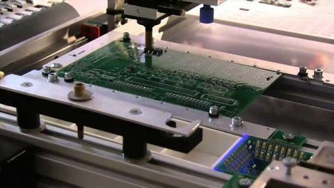
The SMT assembly process is method of applying solder paste on the designated pads of the bare PCB. This solder paste is applied with great accuracy only on those points / pads of PCB where the component will be placed. The component is then placed on the pads exactly as designated by the digital file. This file has (X, Y) coordinates of each component in the design and an automated pick and place robot will use this information to automatically pick components and place them on solder pads.
After the components are placed, the solder paste is then melted in controlled temperature via reflow oven and cooled to strengthen the electrical and mechanical joint between solder pad and SMD component pin. The three main steps in PCBA are 1- Solder Paste Application; 2- Component mounting; 3- Reflow Soldering.
- 1- Solder paste Application:
The solder paste application is done on the automated machine running on a model generated at the designer level. This model will help the machine to apply solder paste exactly on those coordinates where the components will placed and soldered. Hence the machine “prints” the solder paste and forwards the PCB for component mounting and reflow soldering.
Another method of applying solder paste is through solder paste stencil. This stencil is generated by the software like Altium, Eagle and KiCAD. These stencil file is basically a solder paste layer that is included by the PCB designer in his design at design stage. There are many layers in PCB like inner layers and outer layer so a solder paste layer gives exact dimension and location of solder paste and machine is instructed to cut holes or apply solder paste at those points
- 2- Components Mounting
The second step is the mounting or placement of components on PCB. The specialized PCBs are available that performs the job in automatic fashion. Usually a reel of SMD components are fitted inside the machine and components are automatically pick by a vacuum head and placed on PCB after vacuum release. A software generated program same as the one used in solder paste application is used by the automated machine to place components exactly accurately on PCB solder pads.
The fast speed mounting machines generally used to place small SMT components like crystal oscillators, resistors and capacitors with high speed and accuracy. The generic mounting machines are slow pace and are used to place ICs and large / irregular components.
- 3- Reflow Soldering
The third step is to solder the components placed on PCB. The soldering is done in a machine called “Reflow oven”. There are various reflow ovens available that have the options to save heating parameters and timing values to automatically start and stop the reflow soldering process. The reflow ovens are mainly based on Infra-Red Heating, pre heating, soaking and reflux to cooling is done automatically.
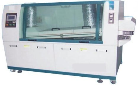
Wave soldering procedure
The molten solder is splashed on the PCB component side and so the mechanical and electrical joints are established. The splash is generated by transforming the molten solder in the form of “wave” by means of mechanical or electromagnetic force. This will create a jet flow of molten solder. The PCB with components is then passed thorough to make electrical connections between PCB pads and components soldering points.
Before this, the components molds are created and components are plugged in. So the PCB with components is thrown into the wave soldering system by means of conveyer belt. After this the solder flux is applied and PCB is preheated. Then wave soldering and cooling is done.
1- Components molding and plug-in components
The main purpose of molding components is that the components are attached perfectly with PCB before going into wave soldering system. So that they do not move and jitter. Now the components are plugged in to the molds and PCB is sent to wave soldering stage.
2- Wave soldering
The solder flux is applied, and PCB goes into preheating. Then the wave soldering is done and cooling is final stage.