ASMT-Mxxx/ASMT-Axxx/ASMTJxxx are Avago's high power LED emitters that provide high luminous flux output in very small package thicknesses. This application note provides a set of guidelines for the user to determine the required thermal capability as determined by other users.
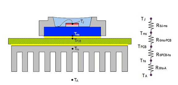
Thermal Resistance Model for a Single LED Emitter ASMT-Mxxx / ASMT-Axxx / ASMT-Jxxx The main thermal paths for power LED emitters are :
LED Die Junction -> Metal Block -> PCB -> Heat Sink -> Ambient
In this model, the thermal path can be modeled using a series resistor circuit , as shown in Figure 1. Heat transfer through the silicone encapsulant and LED body is omitted due to the much lower thermal conductivity compared to the metal block. The total thermal resistance of the system, RqJ-A, can be expressed as the sum of the individual resistances along the thermal path from junction to ambient, as shown below.
RqJ-A = RqJ-ms + Rqms-PCB + RqPCB-hs + Rqhs-A
In some cases without using additional heat sinks, the model can be simplified to:
RqJ-A = RqJ-ms + Rqms-PCB + RqPCB-A
Thermal resistance Rqms-PCB refers to the thermally conductive glue used between the metal block of the LED and the PCB. Unlike other high-power LED emitters that require the use of special thermally conductive compounds such as thermally conductive grease or thermally conductive epoxy, Avago ASMT-Mxxx/ASMT-Axxx/ASMT-Jxxx can be soldered directly to the PCB using solder material as the thermally conductive compound . Since solder is a metal alloy, it conducts heat very well, so its thermal resistance (Rqms-PCB) can be ignored since Tms ≈ TPCB. Thus, the equation becomes:
RqJ-A = RqJ-ms + RqPCB-A

Thermal Resistance Model for Multiple LED Emitters on the
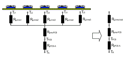
Same Rack When multiple power LED emitters are mounted on the same rack (PCB), the overall thermal resistance will be affected due to additional heat from adjacent units. Since all LEDs are mounted on the same PCB, this will change RqPCB-A. Since there are many emitters on the PCB, the RqJ-ms of multiple LED emitters can be reduced to a single total RqJ-ms using the parallel thermal resistance model shown in Figure 2. Calculate the combined resistance of the parallel resistors.

RqJ-ms total = [(1/RqJ-ms1)+(1/RqJ-ms2)(1/RqJ-ms3)…..+(1/RqJ-msn)]-1
where n = the number of LED emitters on the same PCB.
Since RqJ-ms1=RqJ-ms2=RqJ-ms3=…. = RqJ-msn,
RqJ-ms Calculator = [(n / RqJ-ms)] -1 = RqJ-ms / n
If this simple model is used, the total Pd of all emitters must be considered.
RqJ-ms total = (TJ – Tms)/Pd total
where Pd total = Pd1 + Pd2 + Pd3 + ... + Pdn
Edit: Lisa Wang
