
When PCB engineers design PCBs, the problems of "impedance" and "impedance matching" are often involved in high-speed circuit boards or key signals on circuit boards.
First explain what impedance matching is:
The impedance requirement is proposed to ensure the integrity of the high-speed signal on the circuit board. It plays a key factor in the normal and stable operation of the high-speed digital system. In the high-speed system, the key signal lines cannot be regarded as ordinary transmission lines. Considering its characteristic impedance, if the impedance of the key transmission line is not matched, it may cause signal reflection, bounce, loss, and deformation of the originally good signal waveform (overshoot, undershoot, ringing), which will directly affect the performance of the circuit and even Function.
Every time after the engineers have finished drawing the PCB, if there is a PCB with "impedance" requirements, they must attach the impedance requirements (including which lines, how much impedance, how much control error, etc.) to the process requirements file. )
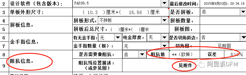
The above is a table of process requirements for PCB manufacturing. Usually, if there are a lot of key signals on the PCB to be impedance, you can attach a separate document to display the line to be impedance controlled, and explain the value to be done and the error, the circuit The board factory will adjust and control these "important signal" lines.
And how did the impedance value come from? Usually, the parameter value is recognized in the chip specification manual, in the program requirements, or in some industries.
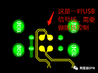
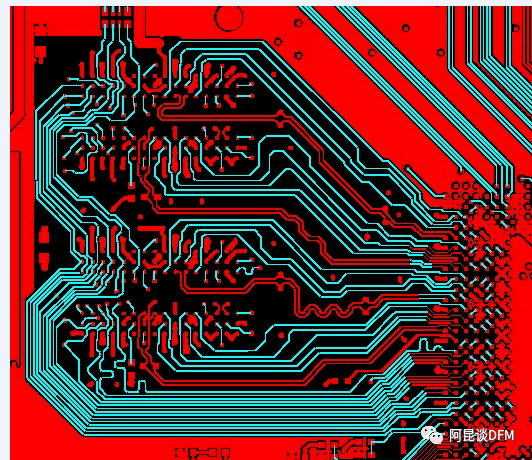
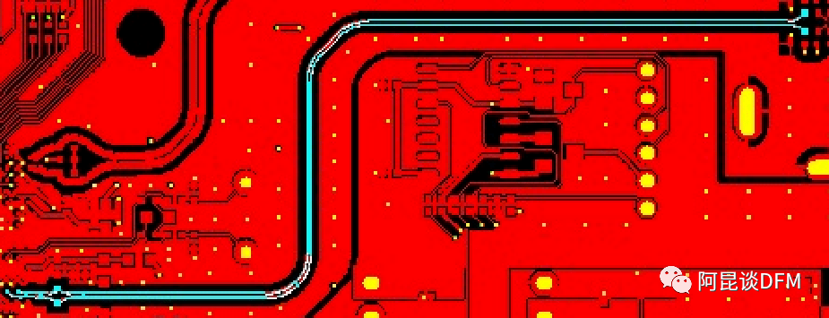
For friends who are not major in electronics, looking at the wiring on the PCB board, in fact, for high-speed signals, the line is not as simple as just connecting from A to B, but also consider the "impedance factor", which is directly related to the signal Whether the complete transmission from point A to point B.
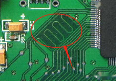
This is the same as the serpentine routing in the above figure. If you don't understand the signal transmission, you can't understand why the line is not straightened directly. Isn't the line segment the shortest between two points, and the line has less loss? No, in electronic circuits, especially high-speed signals, it is about matching. Signal transmission has time. The longer the line, the longer the time. The timing is different, which will affect the performance. None of these matter.
If the impedance does not match, then there will be very large distortion and attenuation during the signal transmission process, which will eventually affect the function, ranging from instability or reduced transmission speed, to direct strikes and direct functions cannot be achieved. The impedance values of different signals are different, and the differential line requires an impedance of generally 100 ohms or 120 ohms, such as high-speed USB and HDMI signals. The single-ended impedance requirements are 50 ohms, 75 ohms, etc. These requirements are determined by the PCB engineers themselves. The PCB board factory will use the impedance software tools to adjust according to your requirements, combined with their materials\PCB file circuit design, and finally Use the device test to get it to the required value.
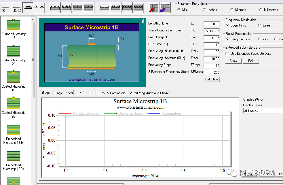
This is the impedance calculation software used by the board factory.
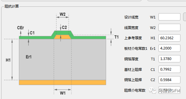
So what are the factors that affect "impedance"? Let's record:
It includes: line width, line spacing, stackup, PCB board dielectric and thickness, etc. These are all factors that affect impedance. The board factory engineer adjusts these values to meet the requirements. In practice, the impedance is mainly controlled by controlling the wire width and stacking (because the PCB substrate \ thickness is a fixed value, the line width \ line spacing parameters are more active).
There are several types of impedance lines. Different types, the objects used in the calculation of the board factory project in the software are different. Everyone should pay attention here. Therefore, it is necessary for PCB engineers to learn how to use PCB impedance calculation software to calculate whether the current designed circuit meets the impedance value (provided that the board parameters used by the board factory can be more accurate).
1. The impedance line is divided into two types: single- ended impedance and differential impedance . The popular point is that it is aimed at a single transmission line and a pair of differential lines.
As shown in the figure below, they are differential impedance, single-ended impedance, coplanar differential impedance, and coplanar single-ended impedance:
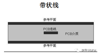
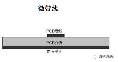
Second, the impedance line is divided into strip line and microstrip line according to the transmission medium .
Stripline: The signal line is located in the medium between the two ground planes (or power supply) (in the inner layer, there are two reference planes). According to the same or different distances between the transmission line and the two ground planes, it is divided into symmetrical strips. striplines and asymmetric striplines.
The characteristic impedance of a stripline is related to the thickness, width, dielectric constant, and distance of the ground plane. The stripline has a power supply or bottom layer on both sides, so the impedance is easy to control, and the shielding is better.
Microstrip line: The transmission line that separates the wire from the ground (power) plane with a dielectric (on the surface of the PCB, there is only one reference plane) is divided into two types of microstrip lines, one is buried (inner layer), one is is non-buried. The characteristic impedance of the microstrip line is determined by the thickness, width, substrate thickness and dielectric constant of the wire. Mainly used for double and multi-layer boards.
Here are a few different types of impedance diagrams:
1. Differential Impedance

The reference ground plane is the same as the single-ended impedance, the only difference is that the line width and line spacing should also be adjusted as required
2. Characteristic impedance (single-ended impedance)
For the impedance of many lines, only the ground plane below, refer to the nearest ground plane to do it, if it is an inner layer line, refer to the nearest 2-layer ground plane to do it.
3. Coplanar impedance (coplanar differential and coplanar characteristics)
3.1 Coplanar Difference
The coplanar differential is surrounded by a uniform copper skin, the distance from the copper skin to the impedance line is the same, and there are rows of via holes on the copper skin, and there are ground planes under and around the coplanar differential impedance line.
3.2 Coplanarity

Having introduced so much, do you have any understanding of the impedance of the PCB? A Kun roughly summarizes:
0. The function of impedance is to ensure the integrity of signal transmission, to ensure that the signal can be completely transmitted from point A to point B without deformation and distortion;
1. Impedance is mainly for high-speed signal requirements;
2. Different signal impedance values are different, which should be confirmed by the PCB design engineer in combination with the scheme requirements;
3. The impedance value is affected by many factors on the PCB;
4. The impedance value is comprehensively calculated by professional impedance calculation software, combined with impedance type, line width, line spacing, plate, laminate, plate thickness, medium and other factors;
5. The board factory tests the final impedance through equipment such as an impedance tester.
-------------------------------------------------- ----------------------
Introduction to Impedance Calculation Tools
The impedance calculation tool software usually used by the board factory is Polar SI9000, but here I recommend an integrated tool that is more convenient for impedance introduction . This is what comes with the DFM review tool for PCBs.
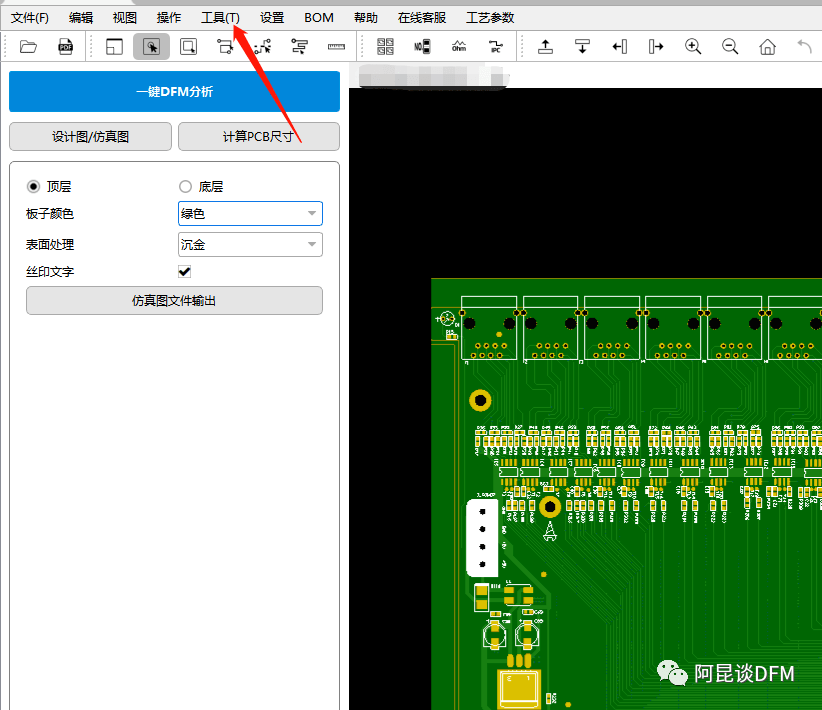
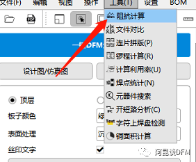
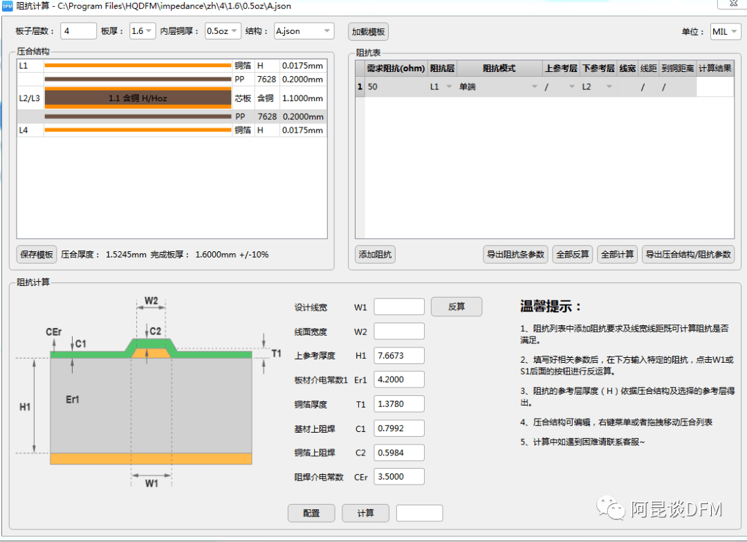
By selecting the appropriate impedance type and PCB related parameters in the software, the impedance value can be calculated, which is simple and easy to use! You can download and use in the following ways!