Components Required
- NodeMCU (ESP-12e)
- L293D or L298 motor driver IC
- 2 x DC motors
- Ultrasonic Sensors (HC-SR04)
- 12v Battery
- 5v Power supply (optional)
L298D motor driver module has an inbuilt 5v supply but if you are using L293D IC, then you have to make a 5v power supply circuit using 7805 IC.
Circuit Diagram
Complete circuit diagram Wi-Fi controlled car using NodeMCU is given below:
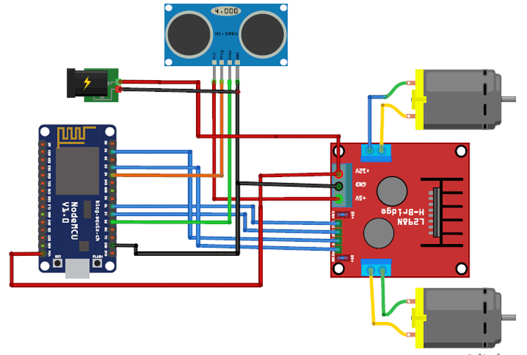
Connections for the circuit is given below:
IN1 pin of L298 -> D6 of NodeMCU
IN2 pin of L298 -> D7 of NodeMCU
IN3 pin of L298 -> D1 of NodeMCU
IN4 pin of L298 -> D3 of NodeMCU
Trig pin of sensor -> D4 of NodeMCU
Echo pin of sensor -> D8 of NodeMCU
Vin of NodeMCU -> 12v battery
5v and GND of sensor -> 5v and GND of L298 module.
12v of L298 module -> 12v battery
To adjust the speed of the motor, use enables pins of a driver module and connect them to the PWM pin of NodeMCU (D2, D5) otherwise connect them to 5v using a jumper.
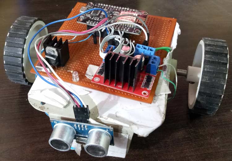
The final setup for Web controlled Robot will look like this
Code and Explanation
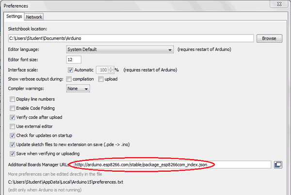
To program NodeMCU with Arduino IDE go to File–>Perferences–>Settings.
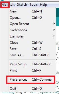
Enter http:// arduino.esp8266.com/stable/package_esp8266com_index.json into ‘Additional Board Manager URL’ field and click ‘Ok’.
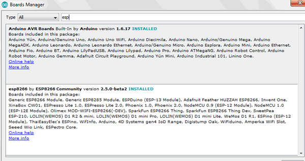
Now go to Tools > Board > Boards Manager.
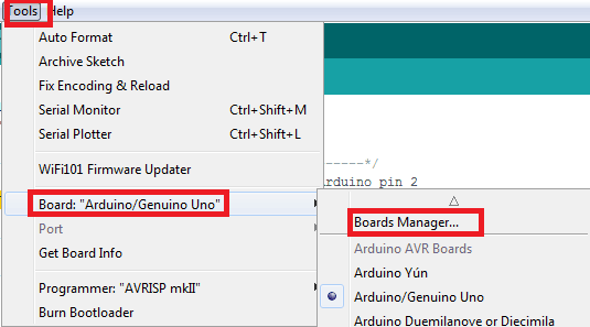
In Boards Manager window, Type esp in the search box, esp8266 will be listed there below. Now select latest version of board and click on install.