
There are several cases in charger failures
- One of the cases that occurs is when we connect a transformer, the LED light that it has lights up properly, its USB cable is placed, but when we connect the cell phone, the LED light that it has turns off.
- Another case is with chargers that the transformer does not have an LED light but when connected to the phone it does not do anything or turn on the phone.
- The third case is with a charger that has its cable included and has an LED light, when I connect it to the plug and to the phone I do not turn on the phone or the LED light it has.
How do you disassemble chargers?
To repair these chargers, the first thing we must do is disassemble them, for this we have two options according to the model of the charger.
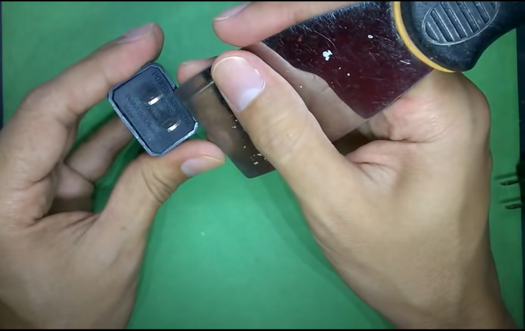
The least complicated case is in the chargers that on one of their sides have something similar to an adjustable lid, then with the help of a very fine and sharp tool, for example a wall spatula, it is introduced in the part where it is inserted. it must be loosened, it is levered to lift the cover and the electronic board is removed.
In the second case, which is a little more complicated because they are glued or sealed with the same plastic, what must be done is that with the help of a cutter or exact one, it is inserted through the most sensitive part, trying to make a notch in the which possibly causes it to break because of what is stuck and then with the help of a sharp tool it is separated by the most vulnerable part, which is the part of the connector to finish separating it and the electronic board is extracted.
How to start the review
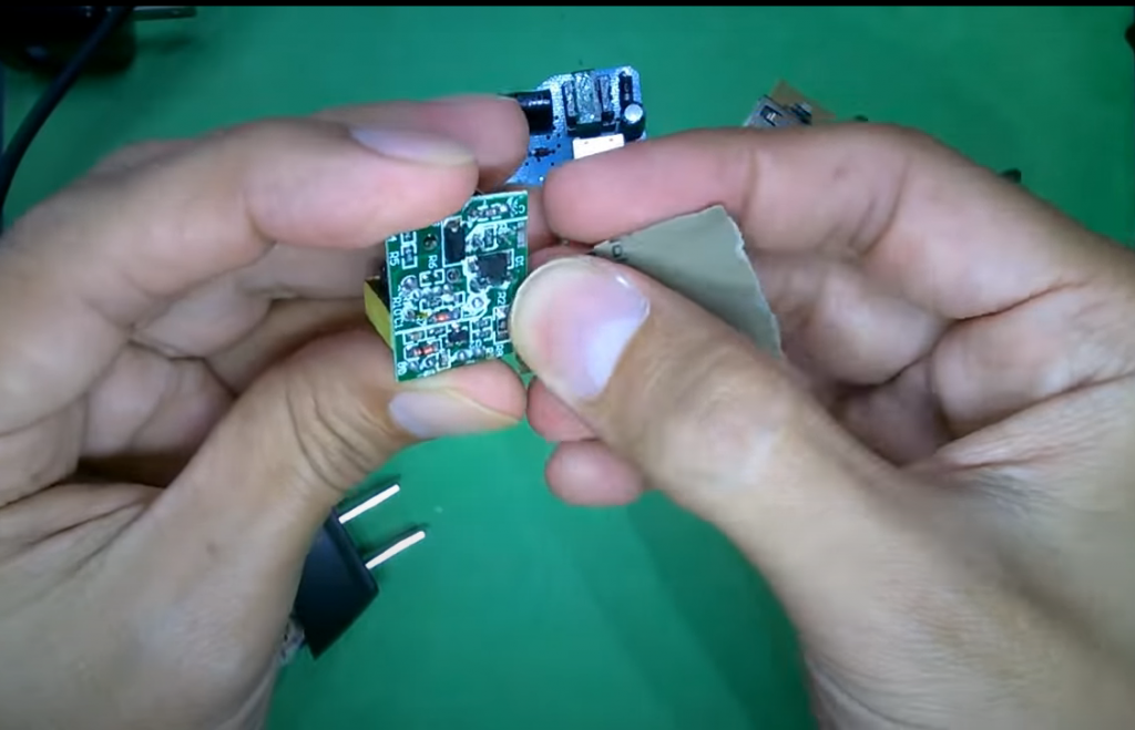
After disassembling the chargers, we observe several plates from different chargers. The first thing to notice, depending on the charger, is that two types of components are going to be obtained on the plates:
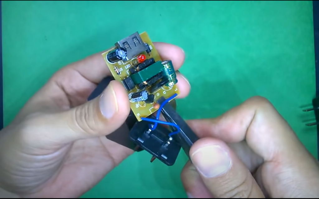
1. Surface mount.
2. Those with a through hole, some plates may have a single component or a combination of both.
The second thing to know is that the chargers are switched source and they work with an oscillation, which we can observe in different ways:
- As Oscillator Chip
- as transistor
We can also observe another element such as the optocoupler which is used for switching power supplies that feed back, so it is needed to measure what the output voltage is and feed back to adjust the current again, this chip is very common.
In the plates we can get four diodes or rectifier bridges, but if we have one we do not have the other since the rectifier bridge has four diodes internally, what they do is rectification, they are very important since it is the stage where current is passed from AC to DC.
Not all faults found in the electronics part are complicated faults, some are very simple faults; solving an electronic problem is observation and knowledge. Hence the procedure to repair a charger after we open or disassemble it.
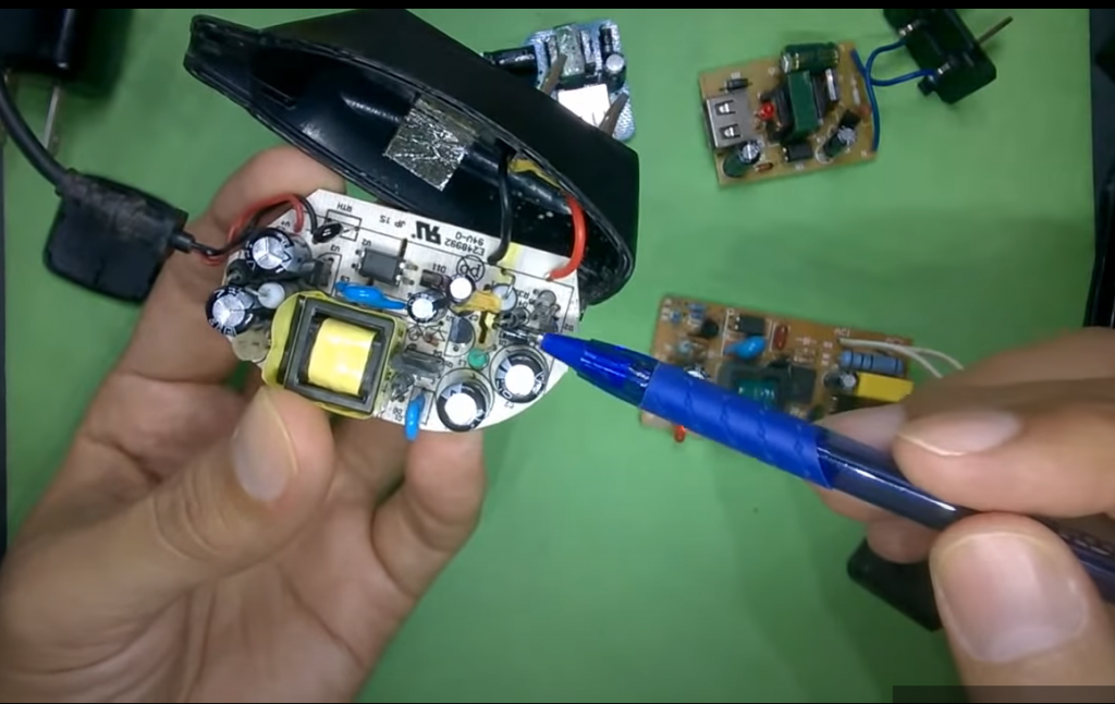
Observe the board and check if there is any visible problem or that can be noticed with the naked eye, since generally when the charger has a problem it is because one or more components is damaged, sometimes the fault is visible to the naked eye and in others it is not visible. they notice.
Which components are damaged first?
The order in which these components can be damaged is first by those through which the most current passes, those are going to be the power elements; then come the electrolytic capacitors because of the way they are built and because of the liquid they work with, which tend to dry out and deteriorate over time; Finally, the diodes would be the elements that can be damaged.
When it is observed and apparently we do not have any damaged components, then the next step is to measure according to the order already indicated, some components are very difficult to measure, such as the integrated circuit and the autocoupler, so what is done is to work by discarding, first the easiest components to measure are measured and if those components measure well, it is concluded that the one that is damaged is the component that we cannot measure but that it is the only one that remains to be measured. That is the way to work. The resistors, which is another of the components that we have, can be seen with the naked eye when they are damaged.
You can start by solving the simplest thing that is the first case that was presented; in which it is observed that in the part that makes contact internally it looks sulfated or dirty.
We can solve this case by sanding the area where the contacts are located with very fine sandpaper very gently, then to verify if the problem is contact with the help of some alligators at the points where there should be a connection, connect the cable USB and connects to the plug and you can see that the phone turns on, that indicates that the problem is only contact, this is the simplest solution.
To observe the other cases we must make a visual analysis of the board and when finding the damaged component that insurance is the problem or there is also the possibility that another element generated that problem, after this we must look for the replacement of this component.
Pumped Capacitors
We can also observe the case of capacitors that can bulge, that is an indicator that the component is damaged, an important thing that must be done is to check around the element that is considered damaged, look for another element that already has faults. That this may be so depends on the type of the element and how it is damaged, if the damage to the element is slight, it is very likely that the element has been damaged by itself; Unlike if the damage is stronger or completely burned, there is a high probability that another element is to blame for that problem. For example, in the event that the element explodes, it could have happened because another element was the one that caused the problem and a second damaged element must be searched for.