
- Visual inspection after SMD Process
- Free AOI Testing
- X-ray Testing for BGA package, Function Testing, etc with extra charges.
- Final visual inspection
Substrate
- The substrate is the base of the board that can create through use of FR4 metallic and ceramic material. All these materials have great features and can work for long timer intervals. Different values of thickness for the base is used.
- Less cost board uses through uses of fewer features of FR4.
Copper Layer
- Copper layers is consists of copper foil that has limited from the board through heat and adhesive reaction
- It exists for both sides of double layers and on one side of a single layer
- To layer, the board explains that there are 2 layers existing in the structure
Solder Mask
- The PCB colors commonly is green due to the solder mask but it can be of other colors. This layer helps to give insulation to the copper traces by avoiding them to make contact with the metallic or soldering
Silkscreen
- A white color silkscreen layer is applied to the upper part of the solder mask. where different letters symbolic representations and numbers are written that are used to connect the components
- Silkscreen of any color can be used but mostly used is black red and yellow
-
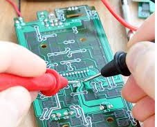
How to Test Circuit Board with Multimeter
- Board testing to find faults is considered a significant parameter. If we do not perform any tests on the board can not get any error existing in the board that will make problems during circuit operation and board utilization
- To avoid any damage and make our board in accurate working there is a need of testing to complete an accurate function of the board
- During the production of the board, tests make sure that to find the errors and these error finding at the right time make our projects accurate
- The PCB designer and manufacturer make sure that accurate testing is done to guarantee the products accurately and fine
- Here are some steps discussed to find the error through the use of a multimeter.
- First of all, set your meter and on the unction needle to AC or DC volts setting. The PCB and net volts will be shown at the meter screen.
- After that do the unplugging of the instrument and housing. then on it and make sure that there is no touch of any wires with your hands
- through using the digital multimeter to find the value of volts and resistance. To perform this stage accurately do the basic tests. Press on the problems of meter to find the test points existing on the board
- Finds resistance or volts value. To attach the resistance of the resistor attach one probe with the endpoint of each resistor
- To find that every part is working correctly perform the previous step for each component on the board. It will indicate us to find the all faulty component existing on the board