
How to Prepare the Programmer
To program the microcontroller, we need a USB ISP AVR programmer, which is a tool used to flash the bootloader and program code to the ATmega328p. These tools can be obtained from any number of sources.
The only requirement for this project is that your USB AVR programmer includes a cable or adapter for using a six-pin ISP header like the one on the robot’s arm.
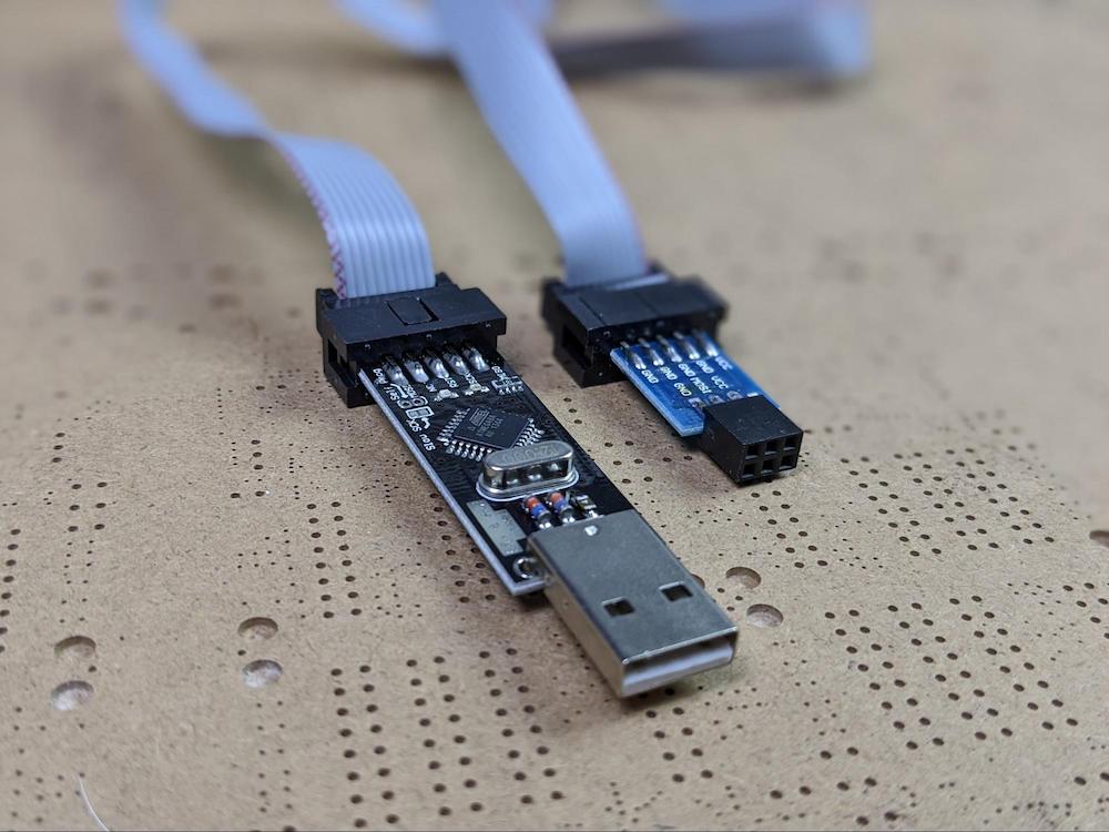
This USB ASP programmer has an adapter that allows it to interface with a six-pin programming header.
For the sake of aesthetics, we did not add any pins to the ISP header on the Maker Pro robot PCB. Instead, in order to connect the USB ASP programmer to the board, we will use a nifty little part called a pogo pin. A pogo pin is a spring-loaded pin that can be used to make temporary electrical connections.
Take six pogo pins and insert them into the six-pin header on the USB ASP programmer. This little mechanism will allow us to temporarily connect a computer to the Maker Pro robot PCB for programming.

The pogo pins allow the USB ASP programmer to be temporarily connected to the PCB without requiring headers to be soldered to the board.
Controlling the Five LEDs
A chunk of the code is dedicated to controlling the five LEDs on the PCB. The robot’s eye LEDs choose a random color to glow each time the NEXT or PREV buttons are pressed.
The LED at the top of the antenna blinks red at random intervals. The two LEDs on the wrench also change each time the QR code changes; they can cycle colors, flow through a rainbow of colors, or individually flow through a rainbow of colors.
Displaying QR Codes
The other major functionality is displaying QR codes on the eInk display. The QR codes themselves are loaded from image files stored on the SD card installed on the back of the eInk display (more on that later).
The QR code allows others to scan the code and view your articles on Maker Pro. On the robot’s legs, there is a NEXT and a PREVIOUS button to change the QR code. In order to avoid damage to the eInk display, the maximum frequency with which the QR codes can be changed is once every three minutes.
Flash the Bootloader
Before code can be uploaded to the ATmega328p onboard the Maker Pro robot PCB, we will need to flash the Arduino bootloader onto the chip.
The Arduino bootloader is a little program that runs on the microcontroller that allows it to understand code being uploaded from the Arduino IDE. When you purchase an Arduino board, it comes pre-flashed with the Arduino bootloader. In this case, though, our ATmega328p is blank. Before we can upload code, we will need to put the bootloader onto the chip, a process called burning the bootloader. This will only need to be done once.
First, we need to set up the Arduino IDE to connect with the Maker Pro robot badge. First, from the Tools > Board: menu, select Arduino Nano. We make this selection because the Arduino Nano also uses an ATmega328p.

From the Tools menu, under Board:, select Arduino Nano.
Then, in Tools > Programmer: select USBasp.

From the Tools menu, under Programmer:, select USBasp.
Now, to flash the Arduino bootloader onto the ATmega328p, we first need to connect the USB ASP programmer to the Maker Pro robot PCB.
If you take a look at the USB ASP programming tool into which we placed the pogo pins, you will find a pin labeled RST. The USB ASP programming pins should be oriented so that this RST pin connects to the pin just above the ISP label on the board’s ISP header, as indicated in the photo below.
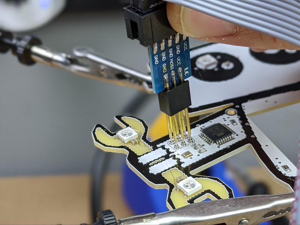
Correct placement of the USB ASP programming pins.
Then, with the USB ASP programmer connected to the Maker Pro robot PCB via pogo pins, select Tools > Burn Bootloader in Arduino IDE.
Burning the bootloader should only take a moment and you will get a success message at the bottom of the IDE once the process is complete. Just make certain to keep the USB ASP programmer in place until the bootloader is finished burning onto the microcontroller or you could risk bricking the chip.

With the USB ASP programmer in place, select Tools > Burn Bootloader.
Upload the Code
Once the bootloader has been successfully flashed onto the ATmega328p, we can upload the actual code that will run the badge.
Normally, you would simply press the Upload button in the Arduino IDE toolbar, however, this functionality requires a USB to serial adapter on the PCB, which our Maker Pro robot badge lacks. Instead, with the USB ASP programmer still connected to the board, go to Sketch > Upload Using Programmer.

To upload code using the USB ASP programmer, select Sketch > Upload Using Programmer.
Just like when you upload code via a USB connection, as you do with Arduino board, the Arduino IDE will verify and compile the sketch, then display a “Done uploading” message when the processes finish.
Review of Progress and Next Steps
Directly programming an ATmega328 microcontroller is a bit different from programming an Arduino board — even one using the same microcontroller. There are several ways to program microcontrollers after they have been assembled into a PCB.
For this project, we used one of the most common methods of programming microcontrollers as part of the electronics manufacturing process: using an ISP header on the Maker Pro robot PCB.
At this point, there is only one task left to finish up the project: creating the QR codes that will be displayed on the eInk module.