
How Differential Pairs Create and Receive Crosstalk
One of the great myths about differential pairs is that they emit no noise and therefore do not create crosstalk. This is completely untrue, and it can be shown by considering the electromagnetic field generated around each trace in a differential pair, as well as the field around single-ended interconnects impinging on a victim differential pair. Due to electromagnetic coupling, we have the following situations involving crosstalk in differential pairs:
- Single-ended to differential pair crosstalk as mixed-mode noise
- Differential pair to single-ended crosstalk as differential mode noise
- Differential-mode crosstalk between differential pairs
Each trace in a differential pair will carry equal and opposite polarity signals. The electric and magnetic fields generated around these conductors will also be equal in magnitude and opposite polarity. The result is that the fields are very strong only near the center region between the conductors, where the electric and magnetic field components point in the same direction and the fields experience constructive interference.
Farther away from the central region between the traces in a differential pair, the fields point in opposite directions, but they are not of equal magnitude. Therefore there will always be some non-zero electromagnetic field strength around a differential pair. This can be seen by looking at the electromagnetic field distribution around a differential pair, as shown below.
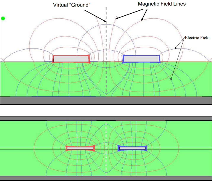
Electromagnetic field lines generated around differential microstrips and striplines.
It is this non-zero field around the differential pair that allows the differential signal to produce crosstalk in nearby interconnects. When designing and routing differential pairs, the goal is to control this crosstalk so that it only produces low level common-mode noise on a victim differential pair. We would also prefer that if the victim net is a single-ended transmission line, the received differential-mode noise is sufficiently low.
Although differential pairs do create some crosstalk, it is important to highlight the noise cancellation properties of differential protocols. One of the original reasons differential pairs were conceived is due to the fact that they can produce less noise away from the center of the pair, and thus there can be less crosstalk than a group of parallel single-ended aggressor nets in a high-speed PCB.
- Differential protocols can have smaller signals swings, so they produce less intense radiated EMI.
- Noise can be controlled by selecting the right spacing between traces in a differential pair.
- Although differential impedance targets can be met without nearby ground, the presence of ground also helps control noise by reducing loop inductance and parasitic capacitance to nearby traces.
- Other strategies like ground poor with via stitching can also be used to control crosstalk if properly designed.
These are important points to remember when routing differential channels in a PCB. With that in mind, let's look at how noise is induced between different types of aggressor and victim nets, as well as the possible strategies for suppressing this noise.
Differential Aggressor, Single-Ended Victim
As was mentioned above, the nonzero field around a differential pair can produce crosstalk in a single-ended net. This received noise may be quite small and will only matter in low-level single-ended signals, which are uncommon in standard logic interfaces. This can be problematic in low-level analog signals, where the induced noise significantly lowers the SNR in the victim net. In standard lower-speed interfaces routed on single-ended traces, this can be less problematic if the guidelines outlined below are followed.
Single-Ended Aggressor, Differential Victim
This is essentially the reciprocal of the above situation. Either differential-mode or common-mode noise can be induced on a victim differential pair, depending on where the field lines impinge between the two pairs. Another reason for the “tight coupling" guideline in differential pairs is that it reduces the loop inductance that would receive differential noise from the aggressor’s magnetic field. The induced noise can also be common-mode noise, which could be suppressed with any of the solutions outlined below.
Differential-mode Crosstalk
Differential pairs can also induce noise on other differential pairs as differential-mode noise. This is problematic as differential receivers are sensitive to differential-mode noise. This noise is received principally through magnetic induction in the cross section between the traces in the pair. At much higher frequencies, the electric field will also couple noise principally through mutual capacitance; this will originate as common-mode noise with some offset between the pairs, the residual of which will be seen as differential-mode noise at the receiver.

Differential-mode noise reception on a victim interconnect.
Differential Pair Design Factors Affecting Crosstalk
The geometry of the two traces in the pair will be the major factor affecting crosstalk involving differential nets. This encompasses everything from stackup design to sizing the pairs.
1. Spacing Between Traces
The spacing between the two traces in the aggressor differential pair will influence noise cancellation. If the spacing in the differential pair is smaller, then the emitted noise and the received noise will be smaller; this is one reason you see the "tight-coupling" guideline when differential pairs are discussed. However, this creates greater deviation between the characteristic impedance and the actual single-ended impedance (the odd mode impedance) in the differential pair. This deviation matters because the odd mode impedance is the reference for termination, not the characteristic impedance and not the differential impedance.
2. Nearby Reference Plane
If the reference plane is brought closer to both nets, then the received noise will also be smaller. This is because the presence of a ground reference closer to the victim and aggressor nets will reduce the mutual parasitic capacitance and inductance between those nets. It will reduce the inductive loop area on both nets, which is beneficial for reducing reception of magnetically-generated EMI from external sources.
3. Dielectric Asymmetry
The presence of dielectric asymmetry in a differential pair will affect forward crosstalk. Greater asymmetry will lead to greater crosstalk because the capacitive and inductive portions of crosstalk will have different magnitudes. If there is less asymmetry in the dielectric constant above and below the differential pair, which can occur in strip lines between two identical prepregs, this will reduce forward crosstalk as the inductive and capacitive responses will have similar magnitude but opposite direction.
4. Coplanar Routing
If the victim is routed in a coplanar arrangement, or as a grounded coplanar waveguide (GPCW), then the ground between the two interconnects can act as shielding. However, this is a more difficult design problem and you should not assume that simply placing copper pour around a victim net will always suppress crosstalk or EMI. Make sure to place sufficient spacing if you plan to route differential pairs through any nearby shielding as the presence of nearby shielding can modify the odd-mode impedance through parasitics, which is undesirable.
5. Distance Between the Aggressor and Victim Nets
By far the most effective way to reduce differential crosstalk is to increase the spacing between the aggressor and victim nets. In real systems, the electromagnetic field always decreases with distance from the source, dropping at a rate of (1/r) or some power thereof. The minimum spacing required for differential pairs depends on all of the geometric factors listed above, but a conservative limit will be a "3W" rule that is commonly cited for high-speed PCBs.
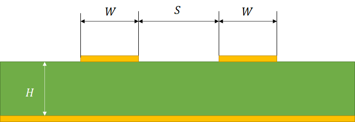
Geometric parameters in differential pair design.
By now it should be quite clear: differential pair design attempts to find a tradeoff between maintaining low noise, consistent impedance, and phase matching across the entire bandwidth of the differential signal. Designing differential pairs to suppress crosstalk is an important part of the need to balance noise, particularly differential-mode noise, that can interfere with signal recovery and produce bit errors. When operating at multi-gigabit data rates, differential pair design takes a careful approach, often requiring evaluation through simulation when designing a high-speed PCB.