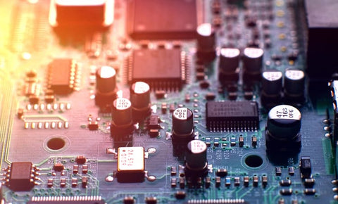
- Controller boards are the heart of any embedded system.
- Most controller boards use surface mount devices (SMDs) due to the reduction of footprint and distance between the components.
- The size of the controller IC package depends on the product size, controller board size, number of I/O pins, thermal stresses, mechanical stresses, and PCB design rules.

Controller boards are the heart of any embedded system
In the course of my career, there have been a few occasions where I have used a controller printed circuit board to perform specified tasks. In one project, a PIC controller was used to create a voltage sag condition in a circuit. In another case, an FPGA board was used to control a power electronic converter. Similar to these examples, we come across a lot of microcontroller-based embedded systems in our daily life—any embedded system that is in use is solely based on microcontrollers, microprocessors, or FPGAs. To achieve the specified function in an intended manner, it is important to design controller boards with the utmost care and precision. In this article, we will discuss embedded systems and microcontroller PCBs in further detail.
Controller Printed Circuit Boards in Embedded Systems
Embedded systems are present in any electronic device or product. The automatic control of temperature in an industrial environment, home automation, and traffic signal control are just a few of the examples of embedded system applications. An embedded system is incorporated into an electronic product to control a function in an intended manner. The specific task of an embedded system is realized using microcontrollers, microprocessors, and FPGAs.
Consider an embedded electronic circuit based on a microcontroller. Most microcontroller boards consist of sections such as power, reset, interfaces such as JTAG, oscillators, I/O peripherals, ADCs, and DACs. The complex logic can be easily executed with the help of microcontrollers in embedded systems.
To perform a function in a specific manner, the embedded system receives input signals. The microcontroller interprets the data received by the I/O peripherals. The data received is processed according to the instructions stored in the program memory of the microcontroller. The data is passed on to the external devices via I/O peripherals and the specific task is completed.
It is necessary and essential to have a microcontroller PCB or microprocessor PCB in an embedded system. Controller boards are the heart of any embedded system, and it is important to give the utmost care and precision to the design (and particularly the size) of these boards.
Controller Board Size
The size of the controller board is an important constraint. Sizing is in accordance with the space available for the controller board in the application system. The sizing should be such that it prevents the overheating of the controller board. The proper positioning of components is significant, and this aspect also influences controller board sizing.
Most controller boards use surface mount devices (SMDs) due to the reduction of footprint and distance between the components. A double-sided PCB with SMD components assembled on both sides is a trend formally followed in controller PCB design. Such controller boards allow for easy testing, repairing, debugging, and reworking, and also make routing simpler compared to multilayer controller PCBs.
Multilayer Controller PCBs
Multilayer controller PCBs offer more degrees of freedom in terms of routing and trace placement. It is challenging to troubleshoot and apply modifications to a controller board when it is designed as a multilayer PCB. However, the typical PCB stackup structure offered by a four-layer controller printed circuit board is a good compromise. The components of controller boards are assembled on the top and bottom layers, and these layers also function as ground planes. The proper position and placement of components can be ensured when soldered in the external layers. The internal layers are set aside as the signal layer and power plane.
Any controller board becomes obsolete without a controller IC. Let's discuss the packaging choice of the controller chip and other components in the upcoming section.
Controller IC Package Selection
In a controller board design, the controller IC package is of great importance, and its packaging also matters. The size of the controller IC package depends on the product size, controller printed circuit board size, number of I/O pins, thermal stresses, mechanical stresses, and PCB design rules. Controller chips may be available in different packaging styles such as leaded quad flat pack (LQFP), quad flat no leads (QFN), dual flat no leads (DFN), ball grid array (BGA), and wafer-level chip-scale packaging (WLCSP).
The selection of the controller IC should match the exact needs of the application and offer high efficiency and cost-effectiveness. QFN packages offer better thermal conduction but have complicated routing and mechanical stresses. BGA packaging supports heat dissipation in controller boards and is suitable for high-speed signals in circuits. Small controller boards can be realized using WLCSP.
Component Package Selection
Most of the components in a controller printed circuit board are passive components. The assembly of the components of the correct package improves the footprint as well as the mutual distance between components. There are several packages, such as 0402, 0603, 0805, and 1206, available in resistors and capacitors, which are the most common passive components used in controller circuit boards. The minimum package selection of passive components should also satisfy the size constraints that can be handled by pick and place (PNP) machines.
There are several other aspects that need attention when designing controller boards: component placement, the separation between analog and digital devices, power supply rail noises, EMI issues, and ground separation. Cadence offers PCB design tools to aid in the design of controller boards.
