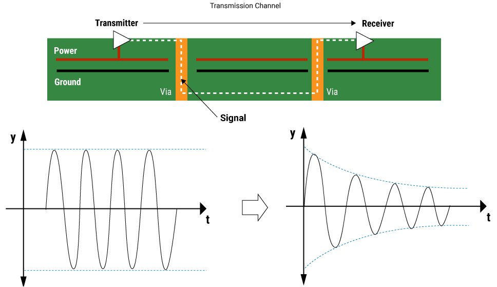
As a signal travels from source to load through PCB conductors, it experiences attenuation due to energy loss due to trace resistance and dielectric losses.
Signal attenuation is the most common term used when high-speed signals propagate across a circuit board. It is one of the main factors that causes signal degradation and leads to signal integrity issues.
What is signal attenuation?
Signal attenuation is a measure of the reduction in signal strength (amplitude and intensity) as a signal propagates through a transmission medium. It is an important property in telecommunications applications because it calculates signal strength as a function of distance.
Lossless signal transmission is achieved when the information provided at the transmitter remains unchanged when decoded by the receiver. Sufficient threshold levels should be met to extract correct information from the signal.
How is signal attenuation calculated?
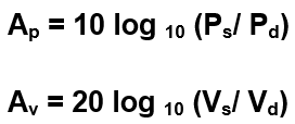
Signal attenuation is estimated in decibels (dB) per unit length of the transmission medium. It can be calculated based on power ( A p ) and voltage ( A v ).
To avoid the chance of fading, the transmitter sends multiple signals to ensure that at least one reaches the final destination, the receiver. But due to the need to send those extra signals, this approach slows down the overall network speed.

Where:
P s is the signal power at the source
P d is the signal power at the load
V s is the signal voltage at the source
Vd is the signal voltage at the load
The lower the attenuation, the more efficient the transmission medium is. Higher attenuation means more signal loss and reduced amplitude at the receiving end.
Attenuation coefficient or attenuation factor
The attenuation factor determines how far a signal can travel and still provide enough data bits or information. It quantifies different transmission media based on how the amplitude of the transmitted signal decreases with frequency. It is given by:
AF = P output/P input
The signal attenuation coefficient depends on:
Transmission medium length
Transmission medium material
Physical conditions
Signal attenuation in transmission lines
In transmission lines, attenuation loss is the combination of two losses: conductor loss and dielectric loss. Conductor losses are due to imperfect conductivity and trace resistance, while dielectric losses are due to the dielectric material.
The signal attenuation coefficient of a transmission line of length "l" is given by:

In dB, signal attenuation is expressed as:

It can also be expressed as dB loss per unit length, that is:

NOTE: Ignore the minus sign, remember it is a dB loss.
The above formula represents the total insertion loss per unit length of the transmission line, which can be written as:

R/Z0 is the loss component proportional to the trace resistance R per unit length, called conductor loss. It is represented by α C. The component GZ 0 is proportional to G – the conductance of the dielectric material and is called dielectric loss. It is represented by α d.

Dielectric losses are negligible compared to conductor losses. Up to 20GHz, the loss tangent associated with the PCB material (i.e. FR4) does not change significantly. This is the main reason why the dielectric loss curve is almost a straight line with frequency. The distance between the transmitter and receiver in the PCB is generally less than 1m. Therefore, it can be assumed that the dielectric loss remains constant over the entire frequency range. As the sum of conduction loss and dielectric loss, the total loss is dominated by conduction loss.
The loss tangent of FR4 materials used in circuit board designs is approximately 0.003.
